Low-speed torque begins with the machine you drive.
Explore a direct-drive approach for conveyors, mills and heavy industrial equipment. The motor is one part of the decision: load, transmission, structure, cooling and control must work as a complete system.
For plant engineering, maintenance and heavy-equipment OEM teams.
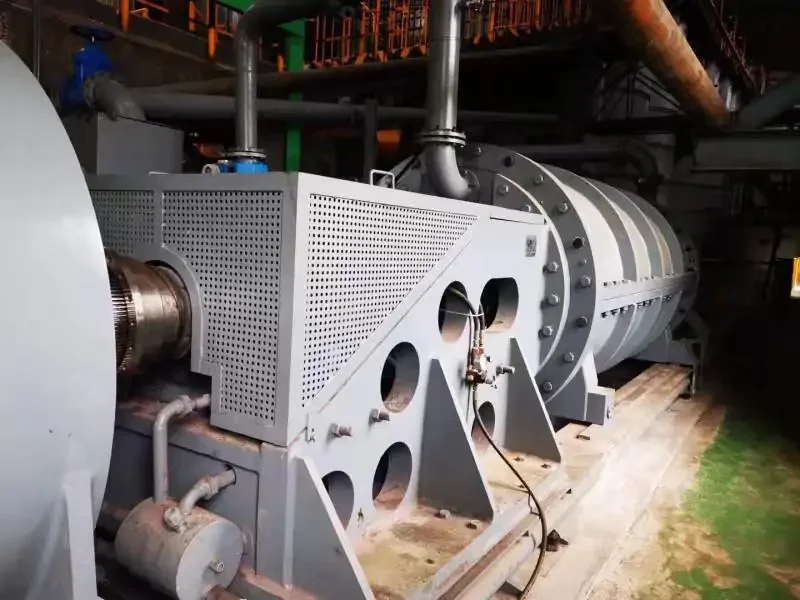
Specify what the new drive removes and what remains.
“Direct drive” describes an architecture, not one universal motor. A proposed solution may remove major mechanical reduction, while couplings, bearings, supports and control systems still need explicit design.
The diagram is conceptual. A project drawing must identify every retained and removed component, support point and torque path.
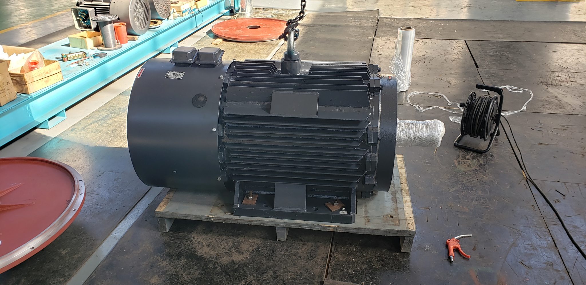
A motor family for gearless projects.
The TYDP route is a starting point for a low-speed, high-torque permanent magnet motor discussion. Actual torque, speed, voltage, cooling and mechanical interface require the application data and model-specific technical review.
Examine TYDPDifferent loads challenge a direct drive in different ways.
A loaded conveyor restart, mill acceleration and variable-flow process impose different torque, inertia and thermal conditions. A site-specific duty envelope makes those differences visible.
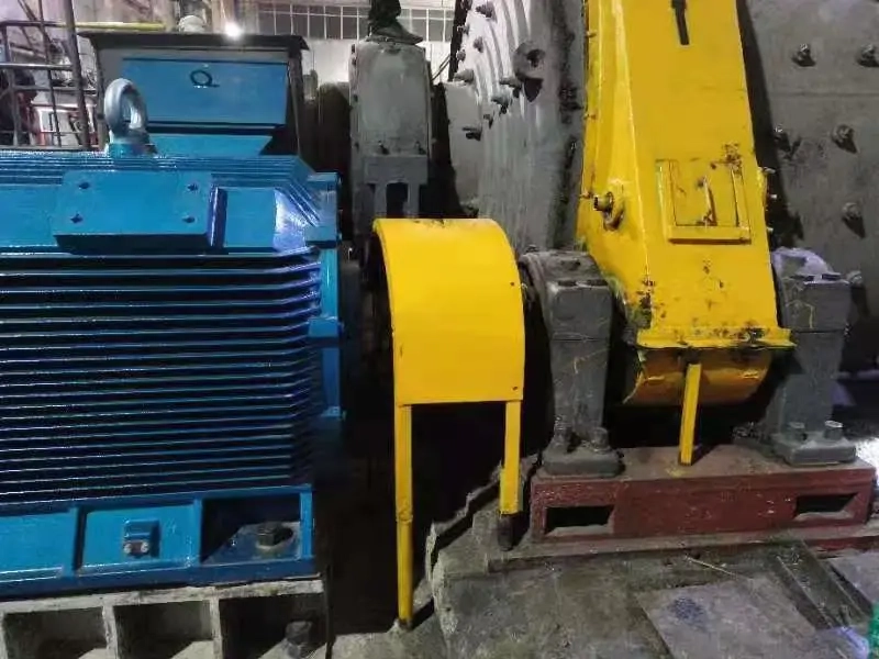
Mills & high-inertia loads
A mill retrofit starts with charge, breakaway behavior, acceleration and the existing drivetrain. A direct-drive proposal must also review shaft support, foundation loads and torsional behavior.
Review applications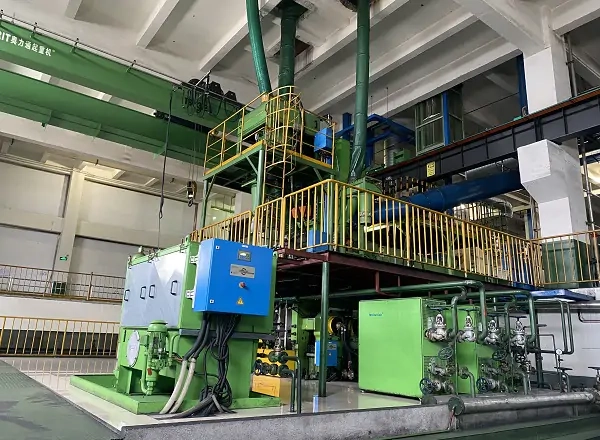
Machine integration
Removing a reducer changes more than speed. The motor arrangement must account for coupling geometry, bearing responsibilities, access for service and the way torque reaches the machine frame.
Review applications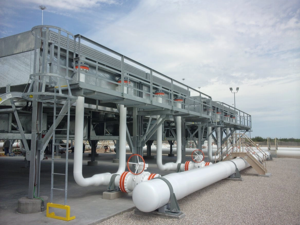
Pumps and air equipment
Variable process demand makes the operating profile important. Capture the process curve, sustained low-speed duty, cooling method and drive control before estimating system benefit.
Review applicationsApplication images show equipment context from ENNENG's archived source material; they do not establish a delivered project or a guaranteed fit.
View all application considerationsBring the shaft, the load and the structure into one review.
Power and target speed alone cannot establish a direct-drive design. The removed gearbox may have provided offset, stiffness or bearing support that the new system must replace.
Speed–torque envelope
Include breakaway, normal running, upset conditions, acceleration time and how long the machine remains at minimum speed. Separate continuous from short-duration peak requirements.
Mechanical boundary
Provide shaft dimensions, coupling arrangement, external loads, bearings, baseplate and lifting access. Mark every component intended for removal or retention.
Electrical & thermal limits
State supply voltage, converter arrangement, feedback strategy, duty cycle, ambient conditions and cooling. Low-speed operation deserves a sustained thermal check.
Acceptance plan
Identify measured input power, output duty, temperature, vibration and operating points. Compare the old and proposed systems on the same boundary.
The motor must fit the plant, not just the calculation.
Large machines bring practical constraints: cable approach, foundation stiffness, alignment, service clearance and safe lifting. A workable retrofit describes these interfaces before a motor frame is selected.
Review low-speed motor considerations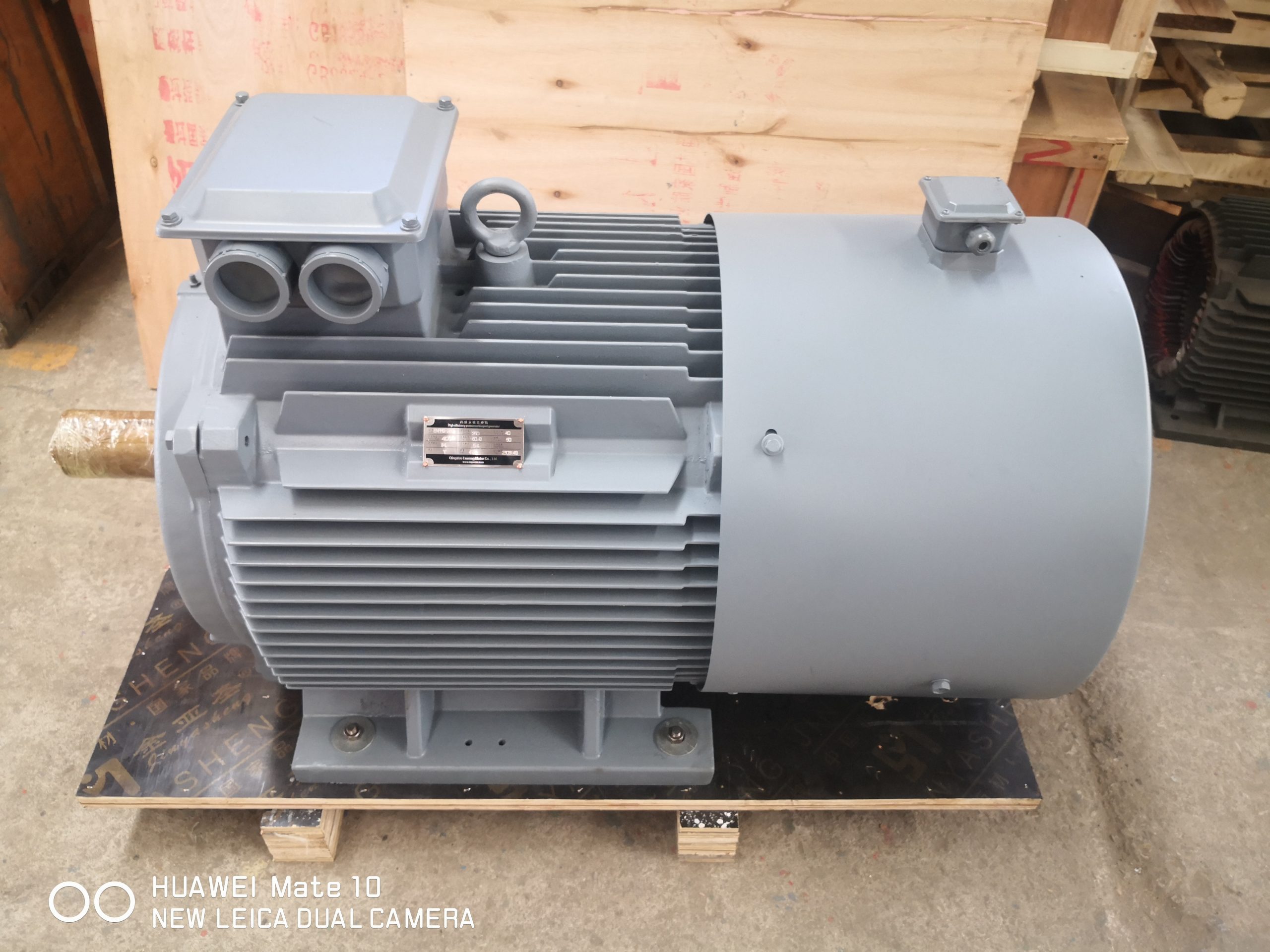
Questions that change the design.
Does direct drive always remove every coupling?
No. It removes or reduces major speed-reduction elements, but a project can still require a coupling, flange or integrated shaft. The proposed mechanical drawing must show the exact boundary.
Why do low-speed applications need a cooling review?
A shaft-mounted fan may provide little airflow at low speed. Continuous torque, minimum speed, dwell time and ambient conditions must be checked together with the cooling arrangement.
What is the most useful retrofit document?
A current general arrangement drawing with shaft, gearbox, foundation and bearing positions is valuable. Pair it with measured speed, load and starting conditions.
What the examples establish.
ENNENG's archived photographs show equipment and industrial context, but a photograph alone does not prove that a particular load has been commissioned with a particular motor. ABB and Siemens describe permanent magnet direct-drive architectures for their own products. Those references support the general concept of low-speed torque and reduced mechanical transmission; they do not establish an ENNENG model's torque curve, installation fit or savings. For any retrofit, document the old and proposed drivetrain, all retained support points and the measurement boundary used to compare results.
Send the present drive layout and the duty it performs.
A sketch, drawing or measured operating profile gives the engineering discussion a concrete starting point. Unknown values can be stated as estimates.